3. Installation
3.1. Ekrano GX Overview of connections
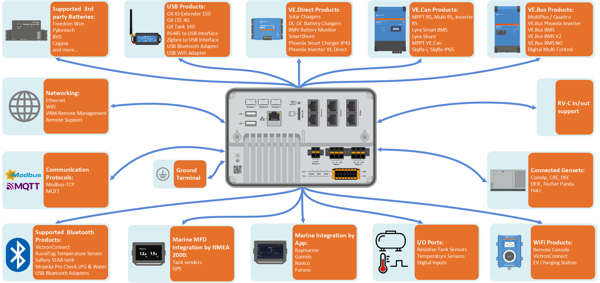
Communication ports | IO | Other |
|---|---|---|
3x VE.Direct | 2x Digital Inputs | MicroSD Card Slot (max. 32GB) |
2x VE.Can | 3x Resistive Tank Level Inputs | Recessed Button for Touch Control |
1x VE.Bus | 2x Temperature Sensor Inputs | Power Supply Port (8 - 70VDC) |
Ethernet | 2x Programmable Relay (NO, COM, NC - current limit: DC up to 30VDC: 3A / AC 125VAC: 1A)) | 7-inch TFT LCD Touchscreen (1024x600 pixels) |
WiFi 2.4GHz (802.11 b/g/n) | Ground terminal to connect Protective bonding conductor | |
Bluetooth Smart | ||
2x USB Host Ports (current limit: 1.5 A @ 5 V shared) | ||
The Ekrano GX supports a maximum of 25 VE.Direct devices, regardless of whether they are connected via VE.Direct ports or USB. However, this limit may be lower in complex systems, for example, those with multiple PV inverters or synchronised inverters. Always include some headroom in your system design to ensure reliable operation. | ||
3.2. Mounting options
The Ekrano GX comes with a solid steel bracket, two rods and wingnuts for mounting from the back and an option to mount from the front only, using the attached springs.
Mounting from the back

Mount the Ekrano GX from the back when it is easily accessible.
Prepare the cut-out as per the cut-out template from the appendix.
Screw the supplied M5 studs with the short threaded end into the rear threads.
Place the EGX in the cut-out and mount the steel bracket with the wing nuts provided.
Tighten the wing nuts. When done correctly, this squeezes the seal to the surface around the cut-out, making it watertight.
Mounting from the the front

Mount the Ekrano GX from the front if it is not accessible via the back.
Prepare the cut-out as per the cut-out template from the appendix.
Mount the supplied springs using the two screws with washers.
Make all necessary cable connections.
Push the springs carefully back and hold them with your fingers while inserting the EGX into the cut-out. Then release the springs. They will snap back once the EGX is fully inserted and hold the device in place. Be careful as those springs are strong and it hurts really bad when they accidentally snap onto your fingers.
Mounting position
Even though the Ekrano GX is watertight from the front (when using the steel bracket) and has a bright backlight, do not to mount it in direct sunlight to prevent overheating and to gain better readability. Mount it horizontally. Portrait mode or automatic rotation is not supported.
3.3. Powering the Ekrano GX
The device is powered via the Power in V+ connector and accepts 8 to 70V DC. It cannot be powered through any other connection (e.g. Ethernet or USB). The supplied DC power cable includes an inline 3.15 A slow-blow fuse.
Powering with a VE.Bus BMS
When using the EGX in an installation with a VE.Bus BMS, connect the Power in V+ terminal on the EGX to the 'Load disconnect' terminal on the VE.Bus BMS. Connect both negative leads to the negative busbar or common battery negative. This is not necessary for the VE.Bus BMS V2 and VE.Bus BMS NG, as both feature a GX-Power output.
Important: Powering from the AC-out terminal of a VE.Bus Inverter, Multi or Quattro
Powering the GX device with an AC adapter connected to the AC-out of a VE.Bus device (e.g. Inverter, Multi, or Quattro) can cause a deadlock:
After a fault or black start, the VE.Bus devices will not boot because the EGX is unpowered.
The EGX cannot boot because the inverter/charger is off, causing a cycle.
Temporary workaround:
Briefly unplug the VE.Bus cable from the GX device to allow the VE.Bus products to restart.
Permanent solution:
Modify the RJ45 cabling. See FAQ Q20 for more information about this.
Recommendation:
Avoid powering the GX device from the AC-out of an inverter/charger. In the event of a shutdown due to inverter overload, high temperature, or low battery voltage, the GX device will also shut down, losing all monitoring and remote access. It is strongly recommended to power the GX device directly from the battery.
Isolation considerations
The GX device connects to various system components. To prevent ground loops, ensure appropriate isolation practices are followed. In most cases, this is not an issue, but proper system design remains essential.
Port type | Cerbo GX | Cerbo GX MK2 | Ekrano GX | Venus GX |
|---|---|---|---|---|
VE.Bus | Isolated | Isolated | Isolated | Isolated |
VE.Direct | Isolated | Isolated | Isolated | Isolated |
VE.Can | Not isolated | 1) | 1) | Isolated |
USB 3) | Not isolated | Not isolated | Not isolated | Not isolated |
Ethernet 2) | Isolated | Isolated | Isolated | Isolated |
1) VE.Can port 1 is galvanically isolated, VE.Can port 2 is non-isolated 2) The Ethernet port is isolated, except for the shield: use unshielded UTP cables for the Ethernet network. 3) USB ports are not isolated. Connecting a WiFi dongle or GPS dongle does not create any problems, as these devices are not powered by an external supply. Even when using a separately powered USB hub, a ground loop may occur. However, extensive testing has shown that this does not cause operational issues. | ||||
Extending USB Ports
The number of USB ports can be expanded using a USB hub. However, the onboard USB ports have limited power availability.
Recommendation
Always use powered USB hubs and select high-quality products to minimise issues.
To increase the number of VE.Direct devices, you can use a VE.Direct to USB adapter. Please see this document for the limit of how many devices can be attached to various different GX devices.
3.4. Built-in 7-inch Touchscreen
The integrated 7-inch touchscreen display provides an instant overview of your system and allows real-time adjustment of settings.Its super slim, waterproof design and simple installation offer flexibility for creating a clean, uncluttered dashboard. No configuration is required; when connected, the device automatically displays the GX overview and menu controls. Display options Display settings are available under: Settings → Display & Language Options include:
Touchscreen operation
|  |
3.5. Deactivating touch input control
To restrict access to the GX system, it is possible to disable touch input control for the touchscreen. This allows the Ekrano GX to be installed in view of the operator, while preventing unauthorised interaction or elevation of access levels via the touchscreen.
Note that this feature only disables touch/mouse control. On the Remote Console, you are still able to control the device with keyboard input.
There are three ways to disable the touch function of the display:
Using the recessed button on the back
Using a momentary push button wired to one of the digital inputs
By using an external USB keyboard connected to the Ekrano GX; The touch function can then be toggled on and off by pressing the Pause/Break key.
If you wish to use this function, ensure that the USB ports and any connected USB keyboard are not physically accessible, to prevent unauthorised activation of the touch feature.
Deactivating touch input control via the recessed button on the back of the Ekrano GX
To deactivate touch input control on the Ekrano GX:
Use a pointed object (e.g. a pen or paperclip) to press the recessed button on the back of the device once.
Touch input is now disabled.
No entries can be made via the touchscreen.
The display will turn off after the period set under Settings → Display & Language → Display Off Time.
Touching the screen will wake it up and display the last active page, but no interaction will be possible.
To re-enable touch input, press the recessed button again.
Deactivating touch input control using a momentary push button
On GX devices with digital inputs, you can configure one of the inputs to control touch functionality using an external momentary push-button.

Configuration steps
Navigate to Settings → IO → Digital inputs → Digital input [number of the digital input]
Enable Touch Input Control
Operation
First press: Touch input is disabled.
No touch interactions are possible.
The display turns off after the configured timeout under Settings → Display & Language → Display Off Time.
Touching the screen will wake the display, but touch input remains disabled.
Second press: Touch input is enabled again.
Important: Pressing the button pulls the GPIO pin to ground. Do not apply voltage to any GPIO pins.
Deactivating touch input control using an external USB keyboard
To control touch input via an external keyboard:
Connect a USB keyboard to one of the USB ports on the GX device.
Press the Pause/Break key to toggle touch input on or off.
For keyboards without Pause/Break key use one of the substitute key combinations mentioned in this Wikipedia article.
3.6. Relay connections
The Ekrano GX has potential-free Normally Open (NO) and Normally Closed (NC) relay functionality. The relay function can be configured via the GX device menu: Settings → Relay → Function.
Relay 1 is particularly important, as it can be used not only for manual or temperature-based triggering (as with Relay 2), but also as an alarm, generator start/stop or tank pump relay.
 |
If the relay function is configured as an Alarm relay, it is possible to reverse the relay polarity via an additional menu.By default, the relay is set to Normally Open (NO). Note: Reversing the polarity to Normally Closed (NC) will result in a slightly higher current consumption of the GX device.
 |  |
Important
Be sure to observe voltage and current limits of the relays as specified in the Technical specifications.